
PID Motor Control
This project implemented a PID Loop on a PIC32 microcontroller to control a motor speed and position. The system was used achieve accurate trajectory tracking of any user inputed trajectory.
Source code: GitHub
Video Demo
System Overview
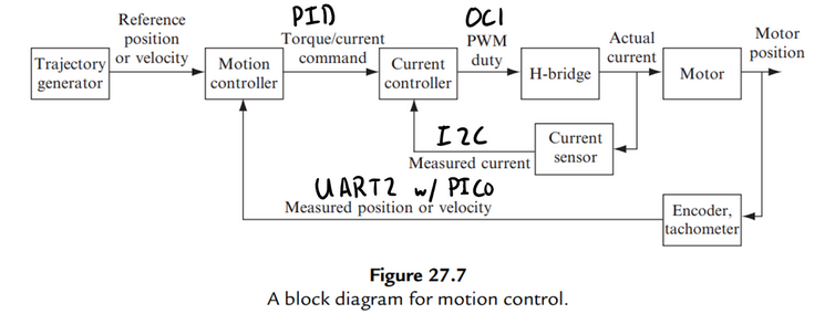
The user can first input a trajectory which is first stored as data for the motion controller. The motion controller uses the data to compute current commands for the current controller, which sends a corresponding PWM signal to the H-Bridge to control the motor. Both the current controller and motion controller work of a PID Loop, the current controller uses the current sensor to measure the actual current going to the motor and the motion controller uses an encoder to measure the position of the motor.
Hardware Schematic
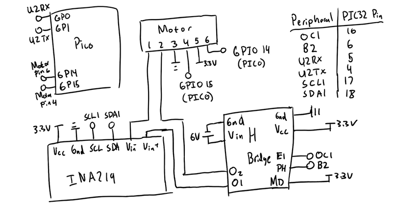
The hardware schematic provides a detailed view of the physical connections used in the system. The PIC32 microcontroller is programmed in C as both the motion controller and current controller for the trajectory tracking system. The Raspberry Pi Pico is used soley for tracking the encoder position of the motor and sending the data to the PIC32 microcontroller. The INA219 is the current sensor used for the current controller which sends its data to the PIC32 over I2C. The H-Bridge is used to drive the motor using a PWM and GPIO pin.
Results
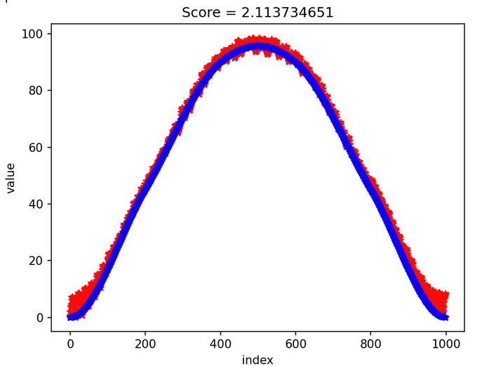
The graph compares the motor’s actual position (red) with the desired trajectory (blue) over time, with the x-axis representing time (index) and the y-axis showing the motor’s angle. The score at the top of the graph quantifies the tracking error, indicating that the system maintained good accuracy throughout the process.